Kits (page 1)
Kit 1 Three Digit LED Counter. Basic low cost counter
![]()
![]()
Two or more counter modules may be plugged together with the 6-pin sockets & harness provided. Uses a single-unit 3-digit LED display.and is built around the 14553 & 14511 chips. Box & battery are provided. The separate COUNTER MODULE shows how to use the Kit as a counter. Has COUNT & RESET switches with debounce circuit built in to eliminate problems from noisy switches. 9V battery operation
Kit 2 LCD Temperature Meter
![]()
![]()
LCD data
sheet - VI302-DP-RC pdf file for Kits 2 and 34.
7106 Data
Sheet
7106
Application Notes
Introduces 3 1/2 digit LCD and the very popular 7106 IC. This IC has been used in low-cost multimeters for over 13 years. We use it to measure temperature using a ordinary signal transistor as the sensor. Data sheets are provided as is a breadboard area so you can extend the circuit to build your own voltmeter, ammeter, resistance meter or extended-range temperature meter. Takes away the mystery of how multimeters work. Box provided. 9V battery operation
Kit 3 LED Dice with Slowdown
![]()
A kit to introduce you to electronics and circuit analysis. Seven LEDs arranged like a real dice face. Push the switch and the dice rolls then slows down. Ingenious circuit design used to minimise components. Uses 14017 & 555. Box included. 9V battery operation
Kit 4 Basic Power Supply Module
![]()
Batteries soon become an expensive way to power your electronic kit and electronic games. This is a basic power supply in a box using two 7805 regulators. Input up to 20V AC from a transformer or power pack. Two regulated outputs are available - one fixed at 5V, the other variable. Good introduction to three terminal regulators
Kit 5 Stairway to Heaven.
![]()
![]()
A game of skill to turn on the Stairway of 6 LEDs as the bi- colour LED flashes. Introduces you to several electronics basic circuits with a surprisingly difficult game to play. Box included. Good introduction to electronics. 9V battery
Kit 6 Roulette LED
![]()
Electronic game. Ten LEDs in a circle. One LED is turned on at a time to simulate the spinning of a roulette ball around the wheel. Uses voltage controlled oscillator circuit. 'Ball' gradually slows down and stops on a number. 'Ball' speed can be adjusted. Uses 9V battery
Kit 7 3V FM Transmitter
![]()
![]()
The most powerful 'bug' available for its size, 3V supply and number of components. Guaranteed to transmit over 100 meters within buildings and to 500 meters in the open. Easily tunable in the FM band. Greater range at higher voltage and better aerial. For an excellent introduction to the theory of 'simple' 2 stage transmitters download FM Transmitter Theory 1.2MB
Kit 8 Light Alarm
![]()
Detects very small amounts of light and sounds the piezo alarm. Put it in your cash box or cupboard. Uses Darlington photo transistor MAL12 and 14011 IC. Educational kit
Kit 9 Oscillator Building Blocks
![]()
![]()
A learning module. Build and experiment with astable, monostable and SR flip-flop multivibrators on the one PCB. 6 LED's & 9V battery-powered. See and understand exactly how each works. Good introduction to electronics. New documentation and PCB 6/2002
Kit 10 Touch/Contact Switch
![]()
Picture of keypad PCB on solder side
Both types of switch are built onto the one PCB so you can see and explore how each type works. A battery can power the touch switch (2 contacts) but a power supply (like Kit 4) must be used for the touch plate (1 terminal) to work. High quality 12V relay rated at switching 240V/3A supplied. Uses 14011 IC
Kit 12 Audio-To-Light Modulator
![]()
![]()
Introduces the Optocoupler-triac MOC3021 and triac. Complete electrical isolation between input audio signal (low voltage circuit) and output light modulation (mains supply voltage levels) is achieved.
Kit 13 Sound Activated Tape Recorder Switch
Can be adjusted to turn on your tape recorder through its REMOTE plug. Has feedback and delay circuit for robust operation. Very sensitive. Proven circuit. Needs 6V plug pack for most stable operation
Kit 14 110V & 240V Mains Powered Strobe Light
![]()
![]()
Kit contains Xenon Flashtube as found on aircraft, camera flash units, signal beacons and disco lights. Adjust to flash from 1 every three seconds to 3 flashes per second. CAUTION: Connects directly to mains power supply. Must be put in a suitable enclosed box before using. Two PCBs for different mains voltage
Kit 15 6-to-12V Piezo Screamer
![]()
![]()
Powerful 6V to 12V piezo alarm. Uses 556, auto-transformer and two piezo alarm elements. Circuit will deliver over 110dB at 1 meter. Uses sweep circuit so there is no need to trim the circuit to match the cavity resonant frequency. We supply a plastic box with two piezo elements (35mm diameter) already mounted in their own resonant cavity. This is part of a commercial alarm unit but it uses our (better!) drive circuit. Ideal alarm unit for Kit 53 (Codepad/Burglar Alarm)
Kit 16 FM Telephone Transmitter
![]()
ZTX320 transistor specification
Miniature transmitter which attaches in series with one of the two lines to your telephone. Transmits over 200 meters to an ordinary FM receiver. Transmits further if the FM receiver is near the phone line. Tune with ceramic trim cap. Uses the phone line as an aerial and power source
Kit 17 LM386 Audio Amplifier Module
![]()
This Kit is designed as a building block in other projects where a battery-powered, variable-gain audio amplifier is required. Up to 2W
Kit K18V2. 9V FM Transmitter
![]()
More powerful FM transmitter 'bug' than Kit 7. Tank oscillator coil built into the circuit board. Can be tuned anywhere in FM band. 9V battery operation. Over 400m range in the open depending on aerial used
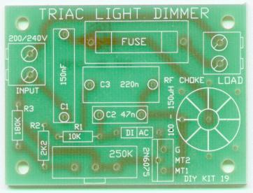
Kit 19 Light Dimmer(200/240V)
![]()
Text-book light dimmer circuit using diac and triac. This circuit operates better than some commercial units. Does not flicker at low light levels. A choke and capacitor are used to reduce RF noise which comes from the non-zero switching of the triac. Caution: Connects directly to 220/240V mains power supply. Must be put in a suitable box for regular operation
Kit 20 Crystal Locked Ultrasonic Movement Detector 1
![]()
![]()
Ultrasonic transducers & 40kHz crystal
Manufacturers data on ultrasonic transducers
Matched 40 kHz transmitter/receiver pair of transducers detects movement at over 7 metres. Separate PCB for mounting the active units. Latch/reset PCB-mounted switch on board. Sensitivity control. 9V battery operation. Transmitter is crystal- locked at 40kHz for maximum efficiency
Kit 21 Two Station Intercom
![]()
![]()
Simple two wire intercom. Each unit with its own speaker, microphone and amplifier (LM386.) Can be modified to a hard wired 'bug'. With 4 strand ribbon cable the power can be sent to the remote 'bug' unit from the receiving unit
Kit 23 Opamp Function Generator
![]()
Good value-for money & simple circuit to generate square, (pseudo) sine and triangle waveforms in the audio range. Uses quad opamp LM348
Kit 24 Logic Probe
![]()
This is the most important piece of equipment for testing and measuring digital equipment. It is usually used in fault finding and testing but can also assist in design work and to find out how digital equipment works. Switch for either TTL or CMOS. Our own modern design using a PUT. Includes detection circuit for very fast pulses. Gives visual (3 LEDs) and audio (piezo buzzer) response.
Kit 25 Mains Time (200/240V)
![]()
A 1 to 5 minute timer for the mains 200/240V power supply using standard electronic building blocks. Uses LM358 and a 2N6075 triac. Has START & RESET buttons. Educational Kit mounts on box provided to show how it works. Caution: Uses mains 200/240V power supply. Kit must be safely placed in closed box for routine use
Kit 26 Fibre Optic Audio Link
![]()
Allows you to send sound through plastic 1mm fibre optic cable. Matched transmitter/receiver pair from Motorola. Two circuit boards with a microphone at one end and a speaker at the other. 14 feet fibre optic cable supplied. Will work over 200 meters
Kit 27 TDA7052 1W Amplifier Module, Mono
![]()
A 1W power amplifier building block designed to be part of a larger project needing a low power battery operated amplifier into an 8 ohm speaker.
Kit 28 Voice Activated FM Transmitter
![]()
ZTX320 transistor specification
A sound activated switch and an FM transmitter joined together to make a voice activated FM transmitter. Set the level of sound that it will respond to. Two stage transmitter needs tuning to get best results. Tuning Kit and instructions enclosed. Transmits up to 1 km in the open depending on the aerial used
Kit 29 Combination Lock
![]()
An introduction to a basic but fully working combination lock. Separate touch pad with 9 pads. Lock is reset if an incorrect digit is pressed. Relay is capable of switching 250V. 12V operation. Robust and versatile
Kit 30 PIR Movement Detector
![]()
![]()
RE200B PIR Sensor used in Kit 30
Essential specs on RE200B sensor
Circuit designed around a recently developed movement IC the KC778B. Circuit utilizes PIR detector and a light dependent resistor (LDR) to provide an optimized circuit that will detect motion up to 6 metres away. Operates on 9-12 VDC. Note that the PIR sensor & the PCB-mounted fresnel lens fit on the other side of the PCB; the solder side. This is to allow the unit to be mounted inside a container with the detecting lens poking out and the controls facing inside the box
Kit 31 9V Siren
![]()
A surprisingly loud siren for such a simple circuit. Uses voltage controlled oscillator. 1/2 Watt, 8 ohm speaker supplied. 9V operation. Ideal to attach to an alarm system which needs an sound module
Kit 32 Three Stage FM Transmitter
![]()
![]()
ZTX320 transistor specification
Our most powerful FM 'bug' to date. A two stage FM transmitter with an RF transistor (ZTX320) in the output stage. 9V operation. On/off switch mounted on the PCB
See Kit 32 Report for independent test results on this Kit by Web-surf
For an excellent introduction to the theory of 'simple' 2 and 3 stage transmitters download FM Transmitter Theory 1.2MB
Kit 33 Tape Recorder Switch for Telephone
![]()
This kit uses a FET to switch on a tape recorder when the phone is picked up. It will work with low voltage tape recorders as low as 1.5V. It requires the REMOTE & MIC jacks of the tape recorder to be available. Plugs are provided
Kit 34 3 1/2 Digit LCD Panel Meter (using 7106)
![]()
LCD data
sheet VI302-DP-RC pdf file for Kits 2 and 34
Application
Note for the 7106
7106 Data
Sheet
Make this general purpose 3 1/2 digit LCD panel meter into your own voltage or current meter or custom-make it to measure voltage input from a transducer. Full details are given in the documentation. Uses the very popular 7106 IC. The LCD section of the PCB may be cut off and mounted separately
Kit 36 4 1/2 Digit LCD Counter (using 7224)
This general purpose 4 1/2 digit LCD counter is built around the ICM7224 IC. All the 7224 pins are brought out. You can custom design it for your own counter application VI-509-DP-RC specification
Kit 43 Relay Board for 10A/250V Rated Relay
![]()
K44 Kit 44 Switched Relay Board for 10A/250V Relay
![]()
A transistor switch has been added to the input of Kit 43, allowing it to be controlled by simple logic levels
Kit 45 Relay Board for 2 x 1A Miniature Relays
![]()
Quite often the hobbyist needs to use a relay. The output of some device like a PIR has output pads for the alarm signal which must be connected to a remote switching device. Or sometimes we have a Kit to test which needs a relay connected to it. To fill these needs we have made two Kits which are just a relay, PCB and terminal blocks for the input/output signals. There are many relay pin-outs & drive voltages to select from. We have standardized on two 12V relays from Goodsky. Kit 43 uses a large electro-mechanical relay designed to switch 240VAC/10A. Kit 45 uses two miniature 1A relays
Kit 46 Christmas Star
![]()
New kit which flashes 30 super-bright, red LEDs in a variety of different patterns. The patterns are read from a lookup table in a micro-controller. Electrically the same as Kit 136; it is only the lookup table and the physical layout of the LEDs which are different between them. These circuits would be impossible using normal ICs. Both circuits are used with permission from the designer, Les Grant. All source code is provided
Kit 47 LM383/TDA2002 Amplifier Module
![]()
![]()
A proven & popular power amplifier building block for use in any audio project. Power output is dependent on the supply voltage and load resistance. Over 10W is typical for a 16V supply into a 2 ohm speaker. A 12V supply into a 4 ohm speaker will deliver around 4W. Small heatsink provided. In late 2000 the LM383 was discontinued but the TDA2002 is a direct replacement
Kit 48 Introduction To Class AB Amplifiers
![]()
Using amplifier modules is modern, quick and easy but it teaches nothing about how they work. Here is a Class AB amplifier made from individual components which will deliver several watts of power into an ordinary 8 ohm speaker. Gives hands-on learning about cross-over distortion, bootstrapping, complementary pairs, and push-pull. Detailed explanations given
Kit 49 Crystal Locked Ultrasonic Movement Detector 2
![]()
![]()
Ultrasonic transducers & 40kHz crystal
Manufacturers data on ultrasonic transducers
Our first ultrasonic movement detector - Kit 20 - has been very popular. This is another circuit design which we believe is more sensitive with fewer components. The transducers are mounted on the same PCB as the circuit
Kit 50 25W HiFi Audio Amplifier Module
![]()
Kit contains the essential components to build a hifi amplifier module using the LM1875 IC. Heatsink, speakers and cables are to be supplied by the user
Kit 51 Small 2.5cm x 1.5cm 9V Bug
![]()
Kit 55 Suction Cup Telephone Pickup
![]()
Uses a suction cup to attach to your telephone handset. Picks up the magnetic field produced in the earpiece by both sides of a telephone conversation. Using op-amps is still a bit of a black art & good layout is essential. Feeds into an 8 ohm speaker after amplification. Volume control trimpot built in. Uses an LM358 & LM386 on a single sided PCB
Kit 57 Negative/Positive Ion Generator
![]()
![]()
Ion generator powered by 110-240V mains supply. It uses the standard Cockroft-Walton multiplier circuit - a ladder of diodes and capacitors to pump the output voltage up to the level required. Fuse built into the PCB. Uses ordinary needle work pins as the ion emitters. Neon indicator to show when the power is on. Reversing the 1N4007 diodes makes it a positive ion generator. The user must supply a suitable box for this project. CAUTION: This is a high-voltage, mains supply project. The user must take extreme caution
Kit 58 IR Remote Toggle Switch
![]()
![]()
Waitrony IR Receiver/decoder module General purpose. Not noise protected
pecification sheet for the IR LED
A very useful kit. Everybody has Infra Red transmitters at home - TV remote, video remote, CD remote, etc. Use ANY Infra Red remote to toggle this switch on or off. Relay output rated at 12VDC/10A or 240VAC/5A
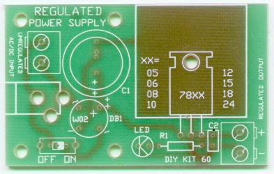
Kit 60 Regulated Power Supply
Kit accepts an unregulated AC or DC input. The user supplies a standard 3 pin voltage regulator from 5 volts (using a 7805) to 24 volts (7824). The full range of possible regulators is: 7805, 7806, 7808, 1810, 7812, 7815, 7818 & 7824. Large heat-sink provided. PCB = 64mm x 40mm (2 1/2" x 1 1/2")
Kit 61 3 1/2 Digit LED Panel Meter (using 7107)
![]()
Make this general design 3 1/2 digit LED panel meter into your own voltage or current meter. Or customize it to measure input from a transducer. Full details given in the documentation. Separate display PCB
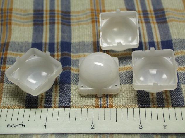
Kit 62 PIR Movement Detector Components
Essential specs on RE200B sensor
Fresnel Lens #8002, pcb-mounted Photo Note the four mounting lugs which fit into holes in the PCB
This kit contains all the hard to get parts for a PIR motion detector. Includes the IR sensor, detector IC the KC778B and a PCB-mounted plastic Fresnel lens. Includes data on IC & Sensor
Kit 63 One Chip AM Radio
![]()
![]()
![]()
![]()
Complete AM radio on a PCB. Tuned radio frequency front-end, single chip RF amplifier & detector and two stages of amplification of the audio signal into a speaker. All components supplied. Coil prewound. Excellent for schools. Uses MK484 radio IC
Kit 64 120 Second Message Recorder
![]()
![]()
Record as many messages as you can in this modern, non- volatile, combined audio processing & memory chip from Information Storage Devices (ISD25120). One button to START/PAUSE & a second button to RESET
Kit 67 DC Motor Speed Controller
![]()
![]()
![]()
![]()
![]()
![]()
Control the speed of any common DC motor rated up to 100V (7A). Operates on 5V to 15V. Uses NE556 to pulse-width modulate a IRF530 MOSFET. In this way motor torque is maintained. Adjustable speed control. Box mounted
October, 2003:. Changed the MOSFET to an IRF530 so 100V motors could be used. But do not draw more than 7A thru the PCB tracks unless you thicken them. Here are the new documents:
Kit 68 Power Supply Module using LM317T
![]()
This is a basic adjustable voltage power supply using the popular three pin regulator, LM317T. You can select any voltage between 1.5V and 30V using a potentiometer. The LM317T is rated at 1.5A so you must use a larger heat sink when drawing high currents