Kits (page 3)
Kit 135 Step-Up DC to DC Converter
![]()
![]()
Designed for countries (like most of Europe) which only have paower supplies to 12VDC. This Kit increases the voltage to 16.5VDC which is needed for out PIC programmers - Kits 81 96 117 and 119
Kit 136 Heart of Love
![]()
A rearrangement of the Star LEDsKit 46 into two hearts. All that has changed is the software lookup table. Electrically the hardware stays exactly the same. This demonstrates the power of using a micro-controller over normal IC's.
These two new kits (kits 46 and 136) flash 30 super-bright, red LEDs in a variety of different patterns. The patterns are read from a lookup table in a micro-controller. Electrically both circuits are the same; it is only the lookup table and the physical layout of the LEDs which is different. These circuits would be impossible using normal ICs. Both circuits are used with permission from the designer, Les grant. All source code is provided
We have found in recent batches of 2051's (used in the Star, Kit 46 and Heart, Kit 136) that the reset pullup resistor in the chip is up the higher end of the specification than the early ones. You should be able to reduce the reset cap down to 2u2 or 1u without problems. In more "serious" designs you would add a 100k pullup resistor which would swamp variation in the chip pullup.
Kit 137 Touch Switch
![]()
![]()
Kit 138 ![]()
Kit 139
![]()
1W Stereo Amplifier Module with DC Volume Control. TDA7053A
Kit 140 Telephone Line Switcher II
![]()
![]()
![]()
The replacement for Kit 86. Remember kit 86 was discontinued because the Motorola K1 uC was discontinued. We now use an Atmel 89C2051-24PI. Use your telephone to switch 4 relays over the phone. Note the MPSA42 is the wrong way around in the first lot of PCBs. Insert it 180 degrees around
Kit 141 Multi Mode Timer
![]()
![]()
![]()
Third in our series of low cost, single-sided PCBs using a micro-controller to replace a handful of ICs if built using traditional cmos ICs. (The previous two were kits 129 amd 154.) Has seven timing modes (all we could think of.) Again like kits 129 and 154, this kit shows the power of the micro-controller. It was reviewed in Silicon Chip, april, 2002 edition. Read it here
These are the time delays possible:
1 - 255 seconds in steps of 1 second
10 - 2550 seconds (42min 30sec) in 10sec steps
1- 255 minutes in 1 minute steps
10 - 2550 minutes (42hr 30min) in 10 minute steps
Timing accuracy +/- 0.01%
Kit 142 14 button Remote Control Unit and Atmel decoder IC in a 12 Channel Infrared Relay Board
![]()
![]()
![]()
This kit was published in Silicon Chip, september, 2002 - Kit 142 12 Channel Infra-Red Remote Control
Kit 143 6 - 10W Stereo Amplifier Module using TDA2005
![]()
We spent alot of time getting the tracks right on this single sided PCB to get the lowest possible THD. Getting the separate tracks to the earth pin is the secret. We tried to do a mono version using the same chip but we could not get the THD to acceptable levels so we cancelled it
Kit 145 Serial Temperature Sensor
![]()
![]()
Kit 145 top overlay of final PCB -Default temperature is degrees Centigrade. Just add a link on the PCB to select degrees Farenheit
Kit 145 is a PC controlled 4 channel temperature meter (either deg C or F) using the serial port, a PIC12C509 and 4 x DS1820. No external power required. We think that each DS1820 may be located over 200 meters away from the motherboard and PC. This is an ideal use for old 386 and 486 computers: continuous temperature data logging. Users will have to massage the input data stream to their purpose. It may be dumped into an Excel spreadsheet, or they can write BASIC programs using the INPUT command to grab the readings. As you can see from the photo there is not much to the hardware. (Developed by James Cameron and you can read his documentation here)
The source code is available from the developer here
Software:
1. You can use term.exe our no-frills terminal program to see the data on the screen. Just run 'term 2400' (and you may have to press Esc to start the display.) The raw temperature data will display on the screen.
2. Or you can use some software the developer of the kit has written. Here are the latest versions: ts11win.zip for Microsoft Windows. Tested on Microsoft Windows 95. Unpack the ZIP file into a directory and run TSL.EXE. Test reports wanted for Microsoft Windows 98, and Microsoft Windows NT.
ts11dos.zip for FreeDOS or MS-DOS. Tested on MS-DOS 4.00.950 on a 386/25 using floppy disk only, and on a machine with a hard drive. With floppy disk, do not exceed a logging rate of once every two seconds. Unpack the ZIP file onto a bootable floppy or a hard disk directory, then run TSL.EXE. If you have no hard disk partition, ignore the warning message about "c:\cwsdpmi.swp"
C source code for these two programs
Software for Kit 145 was written by James Cameron. Linux and UNIX software for K145 is available on his website
New Windows software for K145 - 4 Channel Temperature Logger here
Monitors, displays and logs temperature information from K145. Freeware
Kit 146 40 Second Message Recorder with Looping Option
![]()
![]()
40 Second Message Recorder with Looping Option. This kit will take any ISD DIP chip from ISD2540 to ISD25120. A switch will loop the first message continuously
Kit 148 uC Timer
![]()
![]()
![]()
Simple Photographic Timer
Stopwatch with Pause
40KHz Auto Ranging Frequency Meter
Programmable Down Timer from a maximum of 10,000 minutes
Programmable Down Timer from a maximum of 10,000 hours
Open collector output is used k148. For a discussion of open-collector output get this text file
Silicon Chip published this kit 11/2002 issue. Read the article here
The software author Frank Crivelli has written one-off software variations for Kit 148. They are listed here. Please contact Frank direct if you want some special software for Kit 148
March 31, 2004. Frank has added a Mode 5 to three firmware chips of Kit 148: T0 T4 and T5.
![]()
![]()
![]()
![]()
![]()
Kit 152 Multitimer II.
![]()
![]()
Schematic to show how to connect two x K152 together to get very long duration timers - to 20 years
Kit 153 DTMF Tone Decoder


A cheap, simple, audio, 16x1 DTMF Tone Decoder, Kit 153, is now released. It was designed by Frank Crivelli

It accepts input from a microphone or direct from the phone lines through an audio 600R:600R isolation transformer
Here is the wav file we used to test it
Kit 154 Four Digit Presettable Down Counter
![]()
![]()
This kit was reviewed in Silicon Chip, April 2001. Kit 129 and k154. Microcontroller-Based 4-Digit Counter Modules
Note the kit is a COUNTER, not a timer. A counter counts events - in this case it counts each time the input is connected to ground. A timer counts down in time (hours, minutes or seconds) when the input is triggered
Kit 155 Stereo Tone Control
Kit 156 Dual HI/LO Switched Relay Board
![]()
![]()
Will now fit DIN rail connector. Two LEDs added
Kit 157 Rolling Code 2-Channel UHF Remote Control


This is state of the art. Up to 15 Tx units can be learnt by one Rx unit. A complete description of what rolling code is is referenced. For more on using KEELOQ to generate hopping passwords see AN662 and AN665 by Microchip. Do a google.com search on '433.9mhz', 'lipo' for more information about the transmitting band
We also sell the Tx/Rx units separately as Kit A17.  We also sell K157 assembled and tested.
See Kit 180 for a 4-channel version of this kit and K181 for a 10-channel version.
Kit 158, Bi-polar Stepper Motor Driver kit

March 14, 2005. Kits 113 158 179. Peter Simmonds has developed a visual basic program with source code which can interface PC running windows to the stepper motor kits K113, K158 and K179 via the parallel port. It uses a high speed timer componentRSTimer. Both the source code and RSTimer are available for free at here
Kit 162 6V DC Xenon Flasher
![]()
6V DC Xenon Flasher. Uses on-board EE16 transformer. Uses a neon to trigger the Xenon tube flash
Kit 163 12V DC Xenon Flasher
![]()
Ecap version of K163 instead of using MPE capacitor
Uses a sidac instead of a neon tube to trigger the flash. Sidacs represent a unique set of thyristor qualities. The sidac is a bi-directional voltage triggered switch. Some characteristics of this device include a normal 95 to 330 volt switching point, negative resistance range, latching characteristics at turn-on and a low on-state voltage drop. One cycle surge current capability up to 20 amps makes the sidac an ideal product for dumping charged capacitors through an inductor in order to generate high-voltage pulses. Applications include light controls, high-pressure sodium lamp starters, power oscillators and high-voltage power supplies
Kit 164 Telephone Data Logger


This Data Logger stores over 2,800 x 10 digit DTMF numbers. Records all buttons pressed during a call. Time and date recorded. Here is the k164 documentation
Copy of the Silicon Chip article 12/2001 on Kit 164
The kit was also featured in NutsnVolts, 6/2002.
Here is a typical log report:
07-Aug-01 09:01:32,07-Aug-01 09:02:50,2748828821097231880838#02156711#1
07-Aug-01 09:12:07,07-Aug-01 09:14:10,23042250
07-Aug-01 09:37:51,07-Aug-01 09:37:55,
07-Aug-01 09:54:10,07-Aug-01 09:54:28,
07-Aug-01 10:12:55,07-Aug-01 10:13:36,23042250
07-Aug-01 10:27:26,07-Aug-01 10:27:47,
07-Aug-01 10:40:38,07-Aug-01 10:41:18,
07-Aug-01 10:45:51,07-Aug-01 10:46:22,230422501
07-Aug-01 10:49:07,07-Aug-01 10:49:14,88888888
Lines with no numbers pressed are incoming calls. This option can be turned off. The first line is me checking my bank account balances by phone banking. The last line is me opening the door to my apartment building. The 8 digit numbers are local Hong Kong numbers. If I paid for goods over the phone by credit card then all the credit card info would appear in the log.
And if you don't tell your spouse the logger is connected you can monitor who they are calling and for how long.
In june 2002, we noticed ourselves and received complaints about a problem where not every key press was recorded if they were entered too fast. Only about 3% of kits showed this. This was traced to the difference between the 6N139 and 6N138. The problem only happened when we used a 6N138 which happened to be the IC we were mostly supplying. However, we also fixed it for the 6N138 by reducing R22 to 1K from 10K. From 7/2002 we have started to supply a 1K resistor extra in those kits already packed to use for R22.
- Documentation for assembled & tested version with 64K memory.
- Documentation for assembled & tested version with 16K memory.
Kit 165 is Kit74V2 in a nice box and with Dinkle connectors supplied.


Kit 166 Bidirectional DC Motor Speed Controller


Kit 168 the Ultrasonic Wind Speed Meter


All the components fit under the 16 x 2 LCD. Switches S2 and S3 come out from the bottom of the board which hasplastic 10mm standoffs. It uses a 40kHz ultrasonic Tx/Rx pair to detect wind speed. This design was published in EPE, 1/2003. A copy of the original EPE article goes with the kit. To hold the ultrasonics I found that the locally available, disposable chopsticks were excellent. They even had a groove to align the units to directly face each other
Here are the redrawn schematics - jpg. I have kept the same component designators as the original article 

- This is the article that appeared in "Everyday Practical Electronics".
Kit 169 Versatile PIC Flasher

'Versatile PIC Flasher' as published in 12/2002, EPE is available. I have replaced the BC337's and resistors by a ULN2803A. Used with permission. Get zipped hex and asm files here. It is up to the user to arrange the LEDs into the pattern they want. The LEDs have their own 9-45V power supply separate from the supply to the IC's. This kit yet again demonstrates the power of micro-controllers. Imagine trying to do this kit with discrete logic. Five DIP switches set the flash speed, depth of modulation and flash type
- This is the article that appeared in "Everyday Practical Electronics" December 2002
Kit 171 250mW Power Amplifier

Kit 172 Wide Band Synthesised FM Transmitter
Crystal locked at two frequencies determined by on-board crystals
Kit 173 RF Data Link Serial Transmitter


K173 can receive up to 64 characters via its serial port and transmit the message. The serial port baudrate is selectable from 300, 1200, 2400 and 9600. The data format is fixed at 8N1 (8 data bits, no parity, 1 stop bit). Two input modes are available as well as input echo if required. An optional destination address can be automatically inserted into the message before transmitting
Kit 174 RF Data Link Receiver Serial Output

K174 will receive any messages sent by K173 or K175 and output the data via its serial port. The data format is fixed at 8N1 (8 data bits, no parity, 1 stop bit). The data rate is selectable between 2400 and 9600 baud. An optional carriage return/line feed can be appended to the output
K175 Kit 175 RF Data Link Parallel Transmitter Board


K175 monitors 8 digital inputs for change. If change is detected on any input the state of all the inputs is transmitted. An optional destination address can be added to the message before transmitting. The pinout of the input connector allows direct connection to a PC printer port.
K176 Kit 176 RF Data Link Receiver Parallel Output


K176 will receive any messages sent by K173 or K175 and output the data via its parallel port. The pinout of the output connector is the same as a PC printer port, allowing direct connection to a printer. Optional features are included to control a Centronics type printer.
K179 Kit 179 Unipolar Stepper Motor Driver

March 14, 2005. Kits 113 158 179. Peter Simmonds has developed a visual basic program with source code which caninterface PC running windows to the stepper motor kits K113, K158 and K179 via the parallel port. It uses a high speed timer component RSTimer. Both the source code and RSTimer are available for free here
July 27, 2003, fixed output terminal labelling. Get correct labelling here
Kit 180 Rolling Code 4-Channel UHF Remote Control.
This is state of the art. Up to 15 Tx units can be learnt by one Rx unit. There is a complete description of what rolling code is in the article. For more on using KEELOQ to generate hopping passwords see AN662 and AN665 by Microchip. Do a google.com search on '433.9mhz', 'lipo' for more information about the transmitting band.


We also sell the Tx/Rx units separately as Kit A16. 
Kit 181 Rolling Code 10-Channel UHF Remote Control.
Kit 181 uses the same Tx/RX pair as Kit 180 but it uses all 10 defined keypress combinations out of the 4 buttons to activate relays. If you read the technical documention the following keypress combinations give readable outputs: pins 1, 2, 3, and 4 (of course) and the pins 1&2, 1&3, 1&4, 2&3, 2&4, and 3&4 pressed together. A PIC16F628 does ALL the work. It is a perfect demonstartion of how micro-controllers have taken over from cmos logic etc. 

Toggle or momentary mode will be determined by keeping the 1 or two buttons depressed for more than 2 seconds and then that relay will stay in that mode until another >2 sec keypress. Small relays are used to save weight and board area. Get the commented source code and object hex file here.
Kit 186. Power Amplifier DC Supply
Kit 187 Stepper Motor Drive.

The Stepper Motor Chopper Driver is a Bipolar Stepper Motor Drive with easily adjustable current control up to 2A, based on the SGS-Thompson L297 and L298 stepper motor controller and driver IC’s.
Stepper motors are rated by current and and not by voltage. A chopper driver because it is switching on and off current allows a set current to be fed to the coils and not be dependent on the voltage of the power supply. The Chopper Driver also allows for the use of higher voltage power supplies (up to 36V) to overcome the effects of the inductance of the coils giving better performance and a higher top speed.
Kit 188 ISD1740
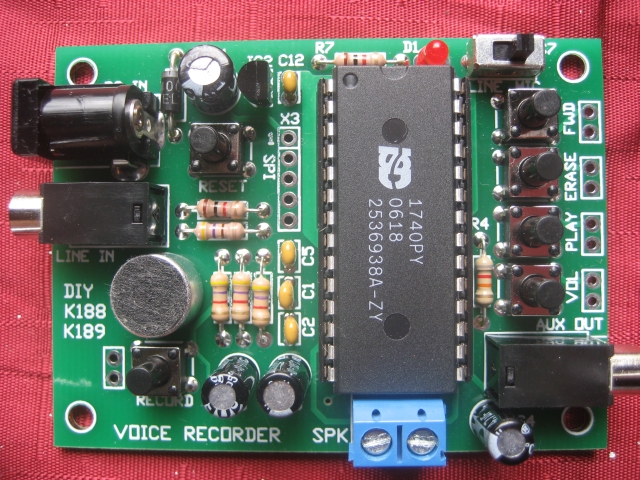
Non-volatile multi message recorder using ISD chips. Just change one resistor for longer duration. Standalone operation using just six onboard bottons. Record via built-in microphone or external line in. Speaker and line out connector. SPI interface. 8-24 VDC.
Kit 189 17120 Second Voice Recorder Module
Non-volatile multi message recorder using ISD chips. Just change one resistor for longer duration. Standalone operation using just six onboard bottons. Record via built-in microphone or external line in. Speaker and line out connector. SPI interface. 8-24 VDC.
Kit190 4-Channel Temperature Monitor and Control

This kit is an extension of our popular K145 Temperature Logger kit. Like the K145 it features 4 temperature inputs using the DS1820 digital sensor. We have also added 4 relays to provide output control. Commands for reading temperatures or controlling relays are sent via the RS232 serial interface using simple text strings. The kit can be controlled by a simple terminal or communications program (such as Hyperterminal) or via the free Windows software available for the kit. This software provides basic thermostat and temperature logging functions.
Software (Updated 21st january 2009)